Reference Documents:
a. Van's Assembly Manual Section 8 , The Fuselage
b. Van's Chapter 5: Construction Materials, Processes and Useful Information
We constructed the fuselage as a kit (i.e. from pre-punched skin panels, angles and fittings) and therefore this is a large segment of our build record. We purchased quick-build wings, most of the assembly of the wings was performed by Van's Aircraft, however we performed the remaining wing assembly, assembled the entire fuselage and empennage and final aircraft assembly, constituting more than 51% of the total assembly required to create our RV-7A. Here are the highlights of fabrication of the fuselage assembly. a. Van's Assembly Manual Section 8 , The Fuselage
b. Van's Chapter 5: Construction Materials, Processes and Useful Information
Fuselage fabrication began with shaping upper longerons from strait angles.
First we needed to make some round-edged jaws for the vice,
and grip the angles with a padded wrench to prevent excessive twisting of the angle during shaping,
Bends were added at drawing specified locations
This section of the angle forms the upper edge of the fuselage, forward of the cockpit, again the fuselage side skin is used as the shaping guide.
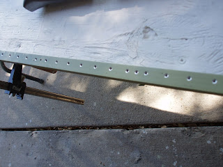
Finally the angles were machine counter sunk, chemical conversion treated and primed in preparation for riveting to the skins.
First we needed to make some round-edged jaws for the vice,
and the shape was checked against the shape of mating pieces (upper cockpit sill shown),
and matched drilled using a drill guide to ensure holes were square with surface
All skin panel fastener holes were dimpled either with a pneumatic squeezer,
or dimpling table:
After assembly of stingers, fitting, skins and the firewall we pre-assembled (described in a separate segment) using pre-punched holes and spring clecos for thin stackups
or draw clecos for thicker ones:all mating parts were match drilled using a drill guide to ensure perpendicularity of the holes and all critical interfaces (such as firewall and spar center section installation) were clamped prior to match drilling to ensure no gaps between mating parts,
and then skin, angles and fittings were disassembled to deburr all rivet holes. Deburring was performed prior to dimpling also. Installing either flush solid rivets (AN426 type) or universal head (AN470 type) is a two-man job centering the rivet set over the rivet head (a task for which Alex became more skilled than I did)
and reacting the rivet gun impact on the other end of the rivet shank using the best suited of any of a variety of bucking bars - my job for most of the fuselage assembly process.
Proper rivet shop head shape was confirmed using a rivet gage:
Particularly critical installations included the spar center section (shown above)
and installation of the firewall assembly we fabricated prior to fuselage assembly (firewall assembly will be described in a separate segment).
and installation of the firewall assembly we fabricated prior to fuselage assembly (firewall assembly will be described in a separate segment).
and the tail cone bulkhead (the horizontal stabilizer is attached to the depicted bars),
We used a rivet squeezer as often as possible as it provides for a very repeatable high quality shop head and no impact loads are applied to the assembly.
Prior to assembly, all aluminum skin panels were treated to combat the corrosive environment we have in our coastal Corpus Christi environment by:
- abrasive deoxidizing using 3M # 7334 scotchbrite and phosphoric acid (metalprep), - chemical conversion treated per MIL-DTL-81706, class 1A (Alodine 1201) and
- primed with Akzo Nobel interior epoxy primer (my favorite paint of any of the topcoats or primers we used during the construction of our RV-7A - nice neutral color, easy to apply a smooth thin coat with any spray gun, quick drying and abrasion and chip-resistant).
The edges of overlapping skin panels were rolled slightly and the final result was very satisfying: (Numbers written on the skin are the rivet shank lengths for a particular line of rivets, which provide for 1.5 the rivet diameter shank protrusion past the inside surface. Proper protrusion results in a compliant shop head. )


No comments:
Post a Comment