Please Read First!

PLEASE READ FIRST
We feel that the information we discuss here is among the best work we have done for our airplane, however, it may not work for yours. Double check and don't take our word for it.

Monday, January 4, 2016

Airworthiness Inspection

Initial airworthiness inspection performed by FAA Aviation Safety Inspector, Airworthiness, identified the following discrepancies to be corrected:

Tie wire bundles to prevent any more than 1/2- inch of movement (especially wires internal to wings):

and tailcone


Route exit wire from L/H  control stick to clear L/H bulkhead:


Provide clearance between elevator pushrod and walls of hole in aft spar:

Before blending passage hole in aft spar:

After blending hole in aft spar:


Install boots on magneto P leads:

Before boot installation: 

After boot installation: 


Verify that rudder cables are tensioned by pilot and co-pilot only (i.e. no springs or tensioners):
Response from Vans Aircraft: "(Daniel)  you're perfectly correct. There is no rudder cable tension...the only thing that connects one rudder cable to the other is the human in the seat.  That's the way it's designed."


Friday, December 25, 2015

Firewall Forward

Reference Documents:
a. Vans Aircraft Assembly Manual, Section 8, Firewall, Firewall Forward Installation
b. Van's Aircraft Manual, Section 5:  General Information
c. Standard Aircraft Handbook (Larry Reithmaier), 1999
d. Drawing 19 Firewall

We included assembly of the firewall and attachment of the engine mount in the firewall forward segment. 

Holes for reinforcement angles and corner fittings are made per drawing 19, as are holes for throttle  and mixture cables, cabin heater inlet and nose gear access hole


Fittings were installed with a squeezer whenever access allowed to achieve the best possible rivet quality and minimize impact to structural parts. 

I like using a drill guide for critical, but there were no instructions in the Van's manual to achieve this.  We machined six (6) of them for the engine mount to firewall/fuselage attachment bolts,

starting with a 3/16 drill,

  and retaining temporarily attachment the firewall to drill the other holes in the pattern, always have a guide to ensure the drill was centered in each of the engine mount bores.  RTV sealant is visible in this image, used to seal out engine compartment from the cockpit. 
until finally the final size was reamed for the 3/8 holes for the AN6-24 bolts (3/8-24 bolts),  (firewall side shown). 
and from cockpit side:


To align the Attachment bolts (3/8-24) were torqued to the low limit for this nut (160 in. lbs.) or as high as 190 in. lbs. as required to line-up the cotter pin hole.

Once the actual firewall is installed , the rest of firewall forward is quite simple and mostly described by drawings 31A, 46A, OP-26, OP-32, OP-33,  .  Noteworthy procedures included installation of fittings into the engine, such as the 45-degree angle fitting for the cockpit oil pressure gage and the the two oil cooler line fitting installed on the engine accessory case.  Both are wet-installed using Permatex high temperature thread sealant.  All cable passages through the firewall were made using interlocking flanged sleeves, one installed from cockpit side and one from engine side and sealed with AMS-S-8802 high adhesion fuel tank sealant .  All cables and hoses were covered with insulation sleeving. 

The IO-360-M1B was attached to the engine mount using the Dynafocal Mounting Kit per drawing 46A.  Of note is that the bolts are tightened to bottom out on the mount spacers, then torqued to standard AN7 value (450 to 500 in-lbs) using a crowfoot wrench.   

Fitting the snorkel to the fuel injection servo:


and inlet filter hole:

Building the baffles around the installed engine using the Van's kit per drawing OP-40. 


and fitting the cowls to fit over the air seal fabric


Proper fit has since been confirmed by bringing engine to normal running temperature to allow for air seal fabric to conform to inside cowl surfaces. 

Monday, December 21, 2015

Rigging - Ailerons, Flaps and Wing Tips

Reference Tech Data:
a.  Section 15 Final Inspection and Flight Test (Van's Aircraft)
b.  Wing Incidence Drilling Simplified (Van's Aircraft)

     Prior to rigging we set the incidence angle of both wings to be equal within 1-degree.  It was only after installing the final wing attachment bolts that I appreciated Van's recommendation to (temporarily) install the wings using smaller diameter "hardware store" bolts - MUCH easier to install, perfect for this phase when making adjustments.   Per the reference b procedure, we suspended plumb bobs (2 on each wing) from the leading edge to a strait line on the driveway, we were able to establish alignment/sweep between the L/H and R/H wings within 1/4-inch (1/2 is the high limit)


 and an equal incidence angle within a 1/2-degree between the two wings,  using a level and Vans's 4-0inch block aligned with the rivet line.  As you can see, ailerons are set at neutral with a strait board  with a strait line on it to attach to two tooling holes in the wing tip rib line and align with the aileron tip.  All this, while 5/8 to 3/4 edge distance around the hole in the aft spar when we drill thru the existing hole in the wing aft spar, into the fuselage rear spar stub, AND keep the retracted flaps as close to the bottom of the fuselage as possible. 


 After all this, we were able to maintain 3/4-inch edge distance around the after spar attachment hole in the aft spar bars.


 After all this, the L/H flap was nearly flush with the lower fuselage, R/H side not as good - about a 1/8-inch gap. 
     Rigging instructions are found on the referenced  drawings and chapter 15 of  Van's Assembly Manual .    Segments in the FAQ section of Vans website were also helpful.  Initial attachment of LH and RH ailerons revealed ailerons were not concurrently aligned with neutral position (strait line between tooling holes in tip rib and trailing edge, created using a strap board with 2-lines drawing along chordwise centerline).  Review of drawing 38 revealed the F-665 (rod between control sticks)was too short (18 1/8 instead of 18 7/8).  Made numerous adjustments, mostly to F-665 linkage between the two sticks, to ensure proper rodend engagement of both the pushrods in the wings, and eventually both ailerons aligned with the neutral position at each wing tip.  The fact that both long wing pushrods ended exactly the same length confirms that the sweep and incidence angle is the same on both wings. 
     The L/H flap fit nearly flush with the bottom of the fuselage skin, on the right side though we have about a 1/8-inch gap (i.e. lower flap skin 1/8-inch too low).  According to Van's (ref. b), the gap is not a big deal, provided everything else is OK, and it is as noted above.  The fix is to slightly bend the inboard edge of the flap until it is flush when retracted, I have also seen some rubber seals that do the job, we decided to go this route to prevent the flap motor from bottoming out metal to metal. 
     Rigging continued to be more involved than expected.  After rigging the ailerons and flaps, the fiberglass wingtips were not in line with them (wing tips were not installed when  setting incidence angle and sweep).  This was fixed by splitting the trailing edge of wingtips and shifting upper and lower halves until alignment was established, then gluing and fastening them in-place with flush-flush solid rivets.


Now flaps, ailerons and wing tips are all in-line:


 and the flap clears the side skin


The aileron stops are 3/4-inch diameter Delrin (chosen for impact strength, abrasion resistance, low water absorption, dimensional stability and machinability) disks installed on the inboard aileron pivot bolts.  First an aluminum spacer was custom machined for the space remaining betyween the fitting lugs after installation of the rod ends and specified washers, then the Delrin disk was machined to be the same length as the aluminum spacer. 


Here is an image of the L/H stop contacting the hinge bracket:
The R/H stop needed to be slightly larger than 3/4-inch (+1/16) in order to contact the bracket, likely because the hinge brackets are hand-made. 

With the stops installed, actual aileron throw was measured to be 25/15 (reference up/down 25/15 to 32/17). 

Next was installation of dual flap position sensors,  one position sensor for the flap position panel display (lights) and one for VPX to be able to set the stops. 


Monday, December 14, 2015

Noteworthy Fuselage Fabrication


Reference Documents:
a. Van's Assembly Manual Section 8 , The Fuselage
b. Van's Chapter 5:  Construction Materials, Processes and Useful Information
We constructed the fuselage as a kit (i.e. from pre-punched skin panels, angles and fittings) and therefore this is a large segment of our build record.  We purchased quick-build wings, most of the assembly of the wings was performed by Van's Aircraft, however we performed the remaining wing assembly, assembled the entire fuselage and empennage and final aircraft assembly, constituting more than 51% of the total assembly required to create our RV-7A.    Here are the highlights of fabrication of the fuselage assembly.     
Fuselage fabrication began with shaping upper longerons from strait angles.
First we needed to make some round-edged jaws for the vice,


 and grip the angles with a padded wrench to prevent excessive twisting of the angle during shaping,

 Bends were added at drawing specified locations


and the shape was checked against the shape of mating pieces (upper cockpit sill shown),

and matched drilled using a drill guide to ensure holes were square with surface

This section of the angle forms the upper edge of the fuselage, forward of the cockpit, again the fuselage side skin is used as the shaping guide. 

Finally the angles were machine counter sunk, chemical conversion treated and primed in preparation for riveting to the skins. 

All skin panel fastener holes were dimpled either with a pneumatic squeezer,


or dimpling table:
After assembly of stingers, fitting, skins and the firewall we pre-assembled (described in a separate segment) using pre-punched holes and spring clecos for thin stackups
or draw clecos for thicker ones:

all mating parts were match drilled using a drill guide to ensure perpendicularity of the holes and all critical interfaces (such as firewall and spar center section installation) were clamped prior to match drilling to ensure no gaps between mating parts,

 and then skin, angles and fittings were disassembled to deburr all rivet holes.   Deburring was performed prior to dimpling also.  Installing either flush solid rivets (AN426 type) or universal head (AN470 type) is a two-man job centering the rivet set over the rivet head (a task for which Alex became more skilled than I did)

and reacting the rivet gun impact on the other end of the rivet shank using the best suited of any of a variety of bucking bars - my job for most of the fuselage assembly process. 
Proper rivet shop head shape was confirmed using a rivet gage:

Particularly critical  installations included the spar center section (shown above)
and installation of the firewall assembly we fabricated prior to fuselage assembly (firewall assembly will be described in a separate segment).

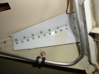
and the tail cone bulkhead (the horizontal stabilizer is attached to the depicted bars),


We used a rivet squeezer as often as possible as it provides for a  very repeatable high quality shop head and no impact loads are applied to the assembly. 

Prior to assembly, all aluminum skin panels were treated to combat the corrosive environment we have in our coastal Corpus Christi environment by:
-  abrasive deoxidizing using 3M # 7334 scotchbrite and phosphoric acid (metalprep),
-  chemical conversion treated per MIL-DTL-81706, class 1A (Alodine 1201) and
-  primed with Akzo Nobel interior epoxy primer (my favorite paint of any of the topcoats or primers we used during the construction of our RV-7A - nice neutral color, easy to apply a smooth thin coat with any spray gun, quick drying and abrasion and chip-resistant).

The edges of overlapping skin panels were rolled slightly and the final result was very satisfying: (Numbers written on the skin are the rivet shank lengths for a particular line of rivets,  which provide for 1.5 the rivet diameter shank protrusion past the inside surface.  Proper protrusion results in a compliant shop head. )